s/n 156 Reg: N1944K // $450,000 - Price Reduced
s/n 156 Reg: N1944K
$450,000 - Price Reduced
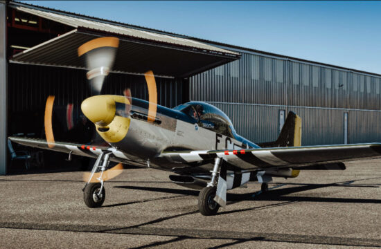
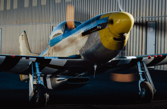
2020 Stewart S-51 Mustang
Aircraft FAQ
Airframe
Engine(s)
Propeller(s)
Avionics
Additional Info
History
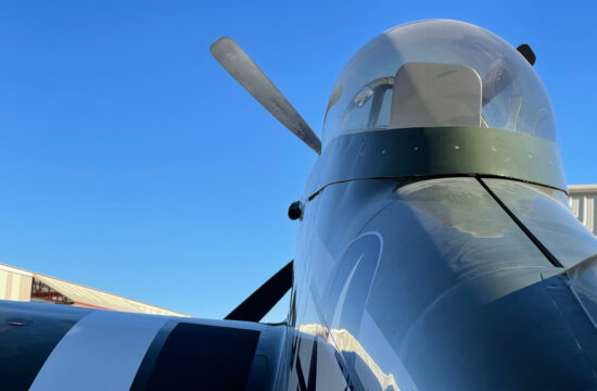
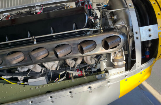
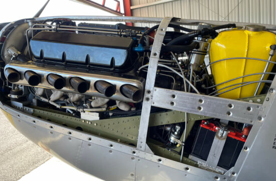
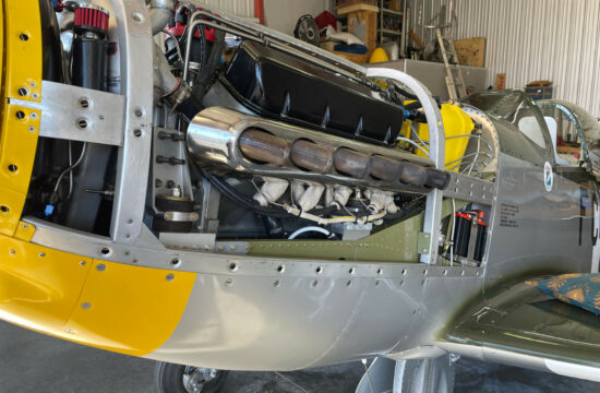
Jim Stewart designed the S51 to be a faithful scale replica of the North American P51. He decided on the scale factor of 70% based on cockpit comfort for himself (5’ 10” 160 pounds) and the available 4 bladed constant speed propeller. The 91” diameter constant speed Hartzell propeller used on the Beech King Air was deemed to be ideal for the S51 aircraft to get the P51 “look”. With a blade tip speed of 850 fps, this propeller at takeoff RPM approximates the tip speed of the full size Mustang. This Hartzell prop has a recommended maximum hub speed of 2200 RPM. In the late 70s, when the design of the S51 began, there was no 70% scale Merlin V12 available. However, due to the “horsepower wars” of the Muscle Car Era, several of the major automobile manufacturers produced V8 engines that approached 500 HP. Jim calculated that the S51 would require an engine in the 400 to 500 cubic inch displacement range. The Mark IV Chevrolet (Big Block) engine proved be the ideal choice for a large displacement engine in a compact package that would fit inside the S51’s engine compartment. A normally aspirated liquid cooled V8 engine properly designed can reasonably produce 1 horsepower per cubic inch when operated in the 4000 RPM region. To produce the 400 to 500 HP required for the size and weight of the S51, yet not turn the propeller past its RPM limits, Jim designed a two spur gear Propeller Speed Reduction Unit (PSRU) with a 2.13 to 1 reduction ratio. Though Rod’s engine is capable of 7000 RPM, the normal maximum engine speed limit is 4680 RPM, which is in fact determined by the maximum RPM limit of the propeller. Jim Stewart’s S51 prototype aircraft initially was fitted with a 454 cubic inch “crate motor” from GM Performance and provided the expected horsepower. This engine was basically “stock” with no changes to the internal components except for the camshaft which was replaced with a marine “left hand drive” unit. This was necessary since the PSRU is a two gear drive, the output shaft (prop shaft) turns in the opposite direction of the input (engine). To get the prop to turn in the conventional direction, the engine must rotate in reverse (counterclockwise when viewed from the cockpit) of the normal direction.
Chevy (BBC) engine routinely run hours on end at 4000 RPM and do it reliably and under warranty. To get as much horsepower as possible out of the engine requires the maximum cubic inch displacement that is practicable. The two factors determining the cylinder’s displacement are the cylinder bore diameter and the stroke of the crankshaft. The constraint for the maximum cylinder bore possible is the distance between the bore centers. In the Big Block Chevy engine, the largest bore size that still maintains an adequate wall thickness between cylinders is 4.500 inches. The other determining factor is the crankshaft’s stroke. There are physical limitations due to the block’s architecture, but the major constraint to the size of the crankshaft’s stroke is the mean piston speed. The larger the stroke, the higher the mean piston speed and the “G” load on the piston, wrist pin, connecting rod, and connecting rod bolts as the assembly accelerates, decelerates, momentarily stops, reverses direction and accelerates again. At 4200 RPM the mean piston speed is 49.58 feet per second and the “G” loading on the piston at Top Dead Center (TDC) is 1420 Gs. Mean piston speed is the major factor for determining the longevity of the rotating assembly. Rod’s engine was designed with a 4.25 inch crankshaft stroke (0.25 inches longer than stock). This is a compromise between the maximizing the engine displacement while minimizing the mean piston speed at the maximum engine RPM. The cylinder’s volume equates to 67.59 cubic inches which calculates out to total engine displacement of approximately 540 cubic inches. I believe that the 540 cubic inch engine is optimum for the S51. Because of the physical limitations of the BBC, the only way to increase the power output without increasing the engine’s RPM is to add a supercharger. The Vortech supercharger that is installed is capable of moving an air volume sufficient for 1000 HP.
ENGINE BLOCK/ROTATING ASSEMBLY
The cylinder block is an aluminum block manufactured by Keith Black Performance. This block is fitted with dry iron sleeves and weighs 100 pounds less than a comparable iron block. The rotating assembly consists of the crankshaft, connecting rods, wrist pins and pistons. The crankshaft is a specially ordered billet steel crankshaft built by Bryant Racing. The crankshaft was machined out of 4340 alloy steel for reverse rotation. The counterweight fairing, oiling holes and journal polishing was performed with the crank’s rotation direction in mind. The connecting rods are made by Oliver Racing Parts, with the length increased 0.25” over stock for a slightly better mechanical advantage as well as reduced side load on the piston skirts. The pistons are built by JE Pistons with an inverted dome to provide a static compression ratio of 7.5 to 1. This relatively low compression ratio was selected because the engine will be supercharged. The rotating assembly’s parts are of the highest quality available and are internally neutral balanced.
CYLINDER HEADS/VALVETRAIN
The aluminum cylinder heads are a special casting by a well known aftermarket cylinder head manufacturer who wishes to remain nameless. These heads are limited production units machined for two sparkplugs per cylinder. They are oval port heads with a 285 cc port volume and 118 cc combustion chamber volume. The narrower oval ports were selected to keep the intake charge velocity high. The intake valves are 2.25” stainless steel and the exhaust valves are 1.88” Inconel. The one weakness in the BBC engine is the stock stud mounted rocker arm retention method. This was addressed by installing a shaft mounted system built by Jesel. The spring rates are relatively mild, with a seat pressure of 150# and an “over the nose pressure” of 450#. The camshaft was custom ground for reversing the engine’s rotation. The camshaft specs are considered “mild” with a wide lobe separation angle of 114 degrees and relatively short intake/exhaust duration of 226/230 degrees, and total lift of 0.586/0.610 inches. This camshaft utilizes hydraulic roller lifters.
OILING SYSTEM
Like the full size P51, this engine has a dry sump oil system with an external camshaft driven pump that scavenges oil from the oil pan and returns it to a firewall mounted supply tank. This oiling system replaced the stock wet sump system due to the performance capabilities of the aircraft. With this engine, the S51 is capable of sustained climbs at a high deck angle. This high deck angle increases the possibility of uncovering the oil pump pick up tube in the oil pan in a wet sump system (stock internal oil pump). Some builders who use the stock oil pump system have installed a pressurized accumulator system to maintain oil pressure in case of the pickup sucking dry. However, the volume of the current commercially available accumulators would only allow 4-5 seconds of oil pressure before the accumulator discharges. Another disadvantage of the wet sump system is that it lacks the capability of removing air from the oil before it is pumped back into the oil passages.
The oiling system in Rod’s engine has provisions to supply a constant stream of oil directed at the underside of each piston to pull heat out of the piston. These piston oilers, as well as a liquid cooled cylinder head, enable the engine to run EGTs of 1500 F with no ill effects. In addition, the added piston cooling decreases the onset of detonation. The oiling system incorporates a device called a Spintric. Using no moving parts, this unit uses centrifugal force to remove air from the foamy oil that is scavenged out of the oil pan. Because of the engine’s high horsepower output and added heat due to the piston oilers, it became necessary to control the oil temperature by installing an air/liquid heat exchanger in the belly scoop ahead of the engine radiator.
COOLING SYSTEM
Rod’s engine’s cooling system uses a custom designed water pump that pumps 70 gallons per minute at 20 PSI through the Stewart provided scoop mounted radiator. This pump is directly driven by the crankshaft and turns at engine speed.This radiator has been shown to adequately cool Rod’s engine, even during a ground static check at takeoff power for 2 plus minutes. A coolant expansion tank is mounted on top of the PSRU, and no thermostat in used in this system. The coolant system maintains a 160 F coolant temperature under normal flight conditions.
FUEL SYSTEM
Rod’s engine has an Air Flow Performance FM300 mechanical fuel injection unit. Fuel is supplied to the unit by an electric boost pump as well as a Romec mechanical fuel pump. Air is drawn through the fuel/air meter by a Vortech centrifugal supercharger belt driven off of the front crankshaft pulley at a 2.5 : 1 step up ratio. The pulleys were designed to limit the supercharger impeller speed to 20% below its maximum at the engine’s maximum speed of 4680 RPM. There is no charge air cooler (Aftercooler) installed.
PROPELLER SPEED REDUCTION UNIT (PSRU)
Originally, this design used engine oil to lubricate and cool the gears and bearings. Rod’s engine installation has it’s PSRU modified to have a dedicated oiling system to lubricate and cool the bearings and gears with gear lube as opposed to engine oil. Gear lube is preferred to manage the high pressures encountered at the gear mesh interface. The oil supply is used to pressurize the prop governor as well as the prop hub. In addition, the cooler gear lube reduces the aluminum gear case expansion which decreases the amount of gear lash increase. The PSRU is driven by the engine through a Stewart designed damping system instead of a quill shaft that other PSRU designs employ.
IGNITION SYSTEM
The ignition system for the engine consists of a Vertex magneto driven by the Accessory Drive Unit and an MSD distributor controlled by two parallel multiple spark discharge modules which are selectable by the pilot.
ACCESSORY DRIVE UNIT
The engine’s accessories are driven by a custom Accessory Drive Unit (ADU). The system includes two 36mm wide HTD belts driven by the crankshaft which in turn drive a combination of pulleys and shafts. These belts, pulleys and shafts are fully enclosed in a case which is bolted onto the front of the engine. The ADU has 7 pads to mount and drive the engine accessories. The dry sump oil pump is case mounted and driven by a drive shaft from the camshaft. The water pump is case mounted and driven directly by the crankshaft. One pad mounts a Jasco 50 amp aircraft alternator that turns at crankshaft speed. Three other pads mount the magneto, the Romec fuel pump and the prop governor, all turning at half crankshaft speed. The remaining pad is currently not used and its shaft turns at 65% crankshaft speed. The supercharger is mounted on the bottom of the ADU.
SYSTEM REDUNDANCY
The configuration of the engine and the ancillary systems were designed to mitigate a fault that would cause an inflight engine failure. A concerted effort was made to anticipate the many possible failure points that could may occur. Probable mechanical and electrical faults were considered and included in the design phase. Two fluid pumps for the engine are mechanically driven by the crankshaft and camshaft. Short of an internal pump failure, if the engine is turning, the oil and water pumps will turn and provide fluid pressure as long as there is a fluid supply. The belt driven mechanical fuel pump is backed up by an electrical boost pump. The magneto is belt driven and the distributor is gear driven by the camshaft. Two separate ignition systems firing two different spark plugs prevent the failure of one system from stopping the engine. Failure of the alternator or a complete electrical failure would not require an immediate landing as the magneto and mechanical fuel pump will keep the engine running. Failure of the prop governor or loss of oil pressure from the PSRU pump will cause the prop to go to a “feather” or course pitch condition. If the engine fails but continues to rotate, the prop governor will still have some control over the propeller (depending on wind milling RPM). In summary, the battery can fall out of the airplane and every drive belt (including the supercharger drive belt) can break and the engine will still run.
ENGINE PERFORMANCE
Though this engine dyno tested at 640 HP, 4750 RPM at 50” Hg MP (uncorrected), 4200 RPM at 42” Hg manifold pressure is the normal maximum power setting for this engine. This engine produces an impressive amount of horsepower and torque at relatively modest RPM. It is my opinion that this engine can maintain takeoff power for an extended period with no ill effects. During testing the engine was connected to the dyno through the PSRU’s prop hub flange so the torque measured (1650 lb/ft) was
2.13 times the engine’s developed torque. Using a very rough rule of thumb for constant speed props of a 1 to 1 relationship between torque and thrust, this engine/prop combination will develop approximately 1600 lbs. of thrust.
IMPROVING THE ENGINE
The design of this engine began nearly 20 years ago. There have been many iterations and changes made as the development progressed. The selection of dual spark plug cylinder heads was made in the interest of redundancy due to the perceived reliability of the available ignition components. The magneto was chosen as a backstop for complete electrical failure. The Air Flow Performance mechanical fuel injection unit was chosen because a carburetor was unsuitable for this application. These choices have proven to be viable as there are two aircraft currently flying with this identical engine configuration without any major issues. The technology advances in the past twenty years has made it possible to significantly improve the engine’s performance regarding reliability, performance and simplicity. The Air Flow Performance mechanical fuel injection performs adequately but due to its design, has very limited “tunability”. The intake manifold that distributes the air into the cylinder head is designed for a carburetor and not optimized for port injection. There is no ability to adjust the amount of fuel dispensed into each individual cylinder, leaving improved power and fuel economy on the table. The main virtue of this system is its simplicity.
The magneto was chosen because of its self-generating capabilities. In practice, the engine has shown a noticeable “roughness” when running on the magneto alone. In addition, there has been nuisance radio noise caused by the magneto’s operation. Confidence in the magneto has decreased to the point that a second control box has been added to the electronic engine system to back up the primary control.
Sales may be subject to local Sales Tax / V.A.T. / G.S.T.
Aircraft maybe subject to prior sale, lease, and/or removal from the market without prior notice.
Specifications subject to verification upon inspection.
Inquire Now
Like what you see? Fill out our convenient form today!

